Tuesday, June 28, 2011

Night 5 - Extruder

After the heat bed I moved on to the extruder. It is here the filament (plastic) is melted and extruded out on the heated bed to build the 3D model.

By now I'm an expert in press fitting :) so there was no problems to press fit the wingnut into the big cogwheel and the 4 NYLOCKs.

However, it turned out to be a real hell to finalise the extruder with the 4 springs in place.

On the picture you can see 3 ball bearings mounted. These are just hold in place by the preassure from the 4 springs, dragging the left plastic peace together with the right one.

The force produced by the springs are so big that I can't fit any filament (plastic) in between the ball bearings.

I did post a question in the forum, but as usual, no one answers...

On the other hand, it feels like something isn't right, maybe I overlooked something....

Day 5 - Heat bed

Today I visited Stig to fix the heated bed and as usual, a few hours later, I left with a couple of more projects in my mind. I think I will need at least 2 more life to do everything :(


Here is the reworked heat bed with one resistor mounted (backside).

Back at home I mounted the resistors that will heat up this plate to about 55C. Here is one of the 4 resistors mounted with cooling paste to increase the heat transfer to the plate.


After all 4 was mounted they are soldered in serial and isolated with a piece of 3.2mm shrinktube.


The free ends will be connected to power later. I'm planning to attach a connector to easily connect and disconnect the power source. The heated bed will consume about 33W and the resistors can stand 15W each (15 x 4 = 60W) so there are a few Watt left to amp up if needed.

Day 4 - Sensors, motors

Yes it was daytime when I begun, well then the night came as usual :)

When I got back from the midsummer celebrations I continued to mount the rollbed, belt drives, motors and sensors.

Here are the 4 stepper motors to move the extruder in X,Y and Z axis. The fourth is to feed the extruder with filament (plastic).


I used the eDrawing to take measurements and adjust the frame to its proper dimensions.

I managed to break one of the sensor brackets but could refit the sensor using the other end instead.

As you can see the Z-Axis and extruder is not attached yet. I need a plummet to align the rods but I can't find any string at home. I did try to assemble it without the alignment, but after mounting things backward and refitting parts 100 times, I got bored and decided to do the alignment first.

Now I have to pay Stig a visit to catch up old times and to use his work shop to fix the heated bed :)

Friday, June 24, 2011

Day 3 - Heated bed

Decided to move on to the heated bed, where all the printing will take place. It turned out that the aluminium piece was not finished. The countersunk holes was not drilled (just a plain hole), but in the online store it is called "you have a choice". Humpf... I need to find some one with a sturdy vertical drill to finish those holes (Stig I'm coming on a visit soon :)

Tomorrow it is midsummer here in Sweden so I will be away for a few days...

Night 2 - Roll bed

Day two disappeared while I was sleeping (odd), but night two was more productive.

I finished the roll bed (Y-Chassis) without any complications. On this bed the heat table will be mounted, where the actual printing will take place. This bed moves in and out (Y-axis).


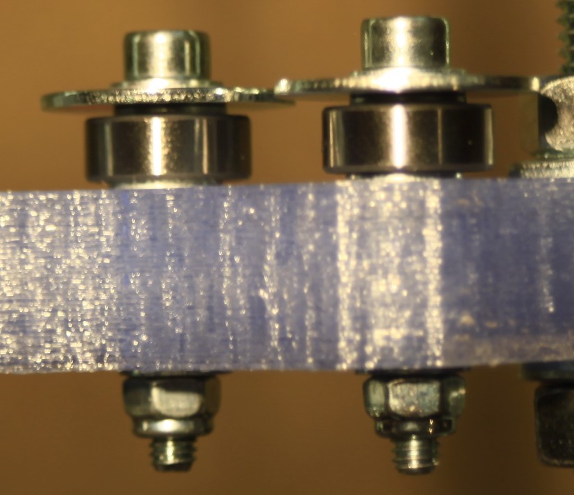
Make sure that the rods can go in between the ball bearings without too much force. The four 40mm screws you see to the left, going through the plastic adjusts the force on the rod. Lose them up if it is too tight.

I then continued on the X-Chassis, so far the most complicated part. This moves the extruder Left/Right (x-axis), and follows the z-axis movements (up/down). Some parts really showed what you can do with this printer.

This is the motor bracket to move the extruder in the X-axis, to the right you can see the fixture for the Z-axis rod. This was the so far most complex part to build with 6 ball bearings in different angels and four M4 insets in between.


The M4 NYLOCKs has to be press-fitted and I used a screw and a hammer to put them into place. In this case they are press-fitted on both sides.


(Right) Here you can see where this block is placed. You can also see the 4 washers squeezed in and the 6 ball bearings that will clamp around the z-axis rod.

The two holes are for the rods where the extruder "sled" will be located.

Don't drill those holes, they are supposed to be clamped tight around the rods.

(Left) the finished piece.


There is a M8 nut press-fitted in the middle. Don't bather trying to press-fit it before you assemble the other parts. It will be nicely press-fitted when you put it all together.

The plastic parts are both flexible and strong, so don't be afraid to break it.


This is the "sled" where the extruder will be mounted. It slides along the rods on 8 ball bearings, controlled by the x-axis motor.


At the other end we find the second fixture around the z-axis rod.


The Z-axis lead screws was quick and easy to prepare. I did the mistake to believe that the rim actually was a part of the support material that should be removed. This resulted in the cog wheel being miss aligned with the driving belt.

After carefully removing the rim, from the support material, with a razor blade it all aligned perfectly.

The left one is with the cut off rim back in place.


That was night two, need to get up earlier tomorrow for midsummer shopping.

Tuesday, June 21, 2011

Night 1 - The frame

Lucky me that we have nights, a bonus time pocket in space. I didn't find  the building description but something almost better; eDrawings!

I kind'a have to figure out for myself in what order I should build, but I can take measurement and point & click for information directly in the eDrawing. As I mentioned before; none of the bags are marked with its content. This also goes for the 24 bags of nuts & bolts... Lucky me I have a calliper.

This made the night fly by when I built the frame. I got more bold and drilled all holes immediately after I checked the size on the drawing. There are basically 3 sizes, 8mm, 4mm and 3mm.


The frame is still put together loosely so I can adjust things into their right place later. It was late and I had to disassemble it a couple of times because I had forgot a washer or two...

The approach I used was to first prepare the sides, then mount all together leaving one side open to mount as the last piece.

Do not drill the "half" holes. These are suppose to lock the rod in place with friction!

The most difficult part at this stage was to get the M4 NYLOCKs inplace.

These are supposed to be inset into the plastic, but the space is miss shaped and I had to use a small pointy rasp to make it larger. Then I could insert a M4 screw from the other side (right) and the then force the NYLOCK in place by tightening the M4 (did this make sense?).

To the right you can see the rod locked in place. DO NOT DRILL THIS HOLE!


The bearings are stacked with a lot of washers and goes in the same way everywhere for the belt drive.

Top - to bottom:
M4 smal washer
M4 large washer
M4 smal washer
Small bearing (qute? :)
M4 small washer
Plastic piece
M4 small washer
M4 NYLOCK

The plastic spring is supposed to have two 4mm holes, one at the side and one through the whole spring. My piece was clogged with plastic residues. Just drill them with a 4mm drill.


Assembled with the sensor bracket.

The most tricky part here was, again, the inset for the M4 MYLOCK for the middle M4 screw, going through the whole spring.

Here I used the same method as before to get the NYLOCK in place.

The sensor bracket will be interesting later when it's time to mount the gap sensor. I would prefer a reflex sensor, smaller and cheaper, maybe I change this later... The space for the sensor cables is very tight (the height of th M4 NYLOCK). In this space the the crimped pins should bend 90 degrees.

I then started with the roll bed, but It was so late I decided to roll into my own bed...

Monday, June 20, 2011

Day 1 - No instructions

Can't find the instruction I was looking for. In the meanwhile I have cleaned up some plastic parts for the frame. The holes needs to be drilled and the sides cleaned of from residues with a rasp.


I used a 8mm drill and carefully drilled the holes on REVERSE at low speed to avoid damages.

Day 1 - The arrival

Today UPS delivered my Mendel parts, a 14Kg brown box. I unpacked it and inspected all the individual bags with excitement.


After some googeling I found some sort of description This was not the one I was looking for. I remember that I saw one with a more detailed step-by-step description, tips and measurements, but I can't find it any more.

If you come across a better description, please leave a comment :)

As you can see, none of the bags are marked. This will make it more interesting :D